Version 11.00
Download User Guide v11.00 PDF
Introduction
The CL-16 Linear Fader Control Surface for 8-Series combines the simplicity of traditional analog consoles with the power and flexibility of digital consoles. This bespoke control surface enhances the experience of cart-based mixing with its intuitive operation, 16 silky-smooth faders, 16 dedicated trims, and a glorious panoramic LCD. All of this is elegantly engineered into a 16.3”-wide compact unit which fits in a cart and operates from 12 V DC.
Key Features
- Compatible with the 833, 888, and Scorpio
- 16 dedicated rotary trim controls
- 16 dedicated faders
- Intuitive design philosophy where channels 1-16 have dedicated, non-banking controls like a traditional analog console, and other important features may be quickly accessed
- 32 multi-function rotary controls for EQ, pan, channels 17-32 gains, bus gains, output gains, and more
- Waveform display for advanced navigation and playback
- Large, sunlight-readable LCD screen folds down for easy and safe storage and transport
- High-reliability, silent, soft-touch buttons for key functions like record, stop, metadata, coms, returns, and more
- Five user-assignable buttons
- Built-in 5-port USB hub (two USB-C and three USB-A) for keyboards, SD-Remote tablet, and other USB peripherals
- 1/4” and 1/8” headphone jacks
- Remote 10-pin connector for custom wiring of LEDs and switches, along with 1/4” foot pedal input
- Connects via USB-B
- 12 V DC-powered via 4-pin XLR (not included)
- 16 ultra-smooth gliding Penny & Giles 100 mm linear faders – best feeling faders on the market
- Quick bottom panel access for field servicing of faders
We are honored to be part of your kit.
Sincerely,
Sound Devices
Panel Views
Top
- Penny & Giles Faders
Adjusts fader levels for channels 1-16. -Inf to +16 dB fader range. Fader gains are displayed on the LCD. Faders can be calibrated by navigating to Controllers > CL-16 > Fader Calibration in the 8-Series LCD and following the on-screen prompts. - PFL/Sel Toggle Switches
Moving the toggle to the left PFLs the selected channel or solos a bus when in Bus Mode. Moving the toggle to the right selects the channel’s setup mode (aka FAT channel) or selects a Bus Sends on Fader mode when in Bus Mode. - Trim/Mute Pots with Ring LEDs
Rotate to adjust trim gain for channels 1-16. Trim gains are displayed in the LCD. Press while holding Menu to mute/unmute channels 1-16. Surrounding ring LEDs provide visual indication of channel signal level, PFL, mute, and arm status.- Variable intensity green, yellow/orange, and red for signal level, pre/post fade limiter activity, and clipping respectively.
- Flashing yellow = channel PFL’d.
- Blue = channel muted.
- Red = channel armed.
- Middle Row Multi-Function Knobs with Ring LEDs
Rotary/press knobs with multiple functions depending on the selected mode. Values and status are displayed in the second row of the LCD. Rotate or press to adjust or toggle different parameters. The surrounding ring LEDs display various status information. - Upper Row Multi-Function Knobs with Ring LEDs
Rotary/press knobs with multiple capabilities depending on the selected mode. Values and status are displayed in the top row of the LCD. Rotate or press to adjust or toggle different parameters. The surrounding ring LEDs display various status information. - Stop Button
Stops recording or playback. Pressing Stop while stopped switches to display the next take name in the LCD to be edited with the Scene, Take, and Notes buttons. - Record Button
Starts a new recording. Illuminates red when recording. - Mode Buttons
Selects various modes to determine what meters and other info is displayed on the LCD and the function of the upper and middle row multi-function knobs and PFL/Sel toggle switches. - Metadata Buttons
Shortcut buttons for quick editing of metadata. Edit Scene, Take, and Notes for the current or next takes. Increment a scene name, circle a take, or delete the last recording (False take). - User-Assignable Buttons
User-mappable to various functions for fast access. Mapped functions are displayed above in the LCD. - Return Buttons
Dedicated buttons for monitoring the various returns in headphones. - Com Send Buttons
Press to talk. Routes the selected slate mic to destinations configured in the Com Send Routing menus. - Meter Button
Press to return to the default home LCD view and current HP preset. Also duplicates the functionality of the Meter button on the 8-Series front panel. - Menu Button
Duplicates the assigned functions of the Menu button on the 8-Series front panel. Hold then press a channel’s trim pot to mute that channel. Also used to mute buses and outputs in relevant modes. - Toggle Switches
Duplicates the assigned functions of the three toggle switches below the 8-Series front panel. - Headphone Knob
Duplicates the functions of the headphone knob on the 8-Series front panel LCD. On Scorpio, hold while pressing the Com Rtn button to toggle on/off the monitoring of Com Rtn 2 in headphones. Press when a channel or bus is soloed to toggle the current headphone preset. Hold during playback to enter audio scrub mode. - Select Knob
Duplicates the functions of the Select knob on the 8-Series front-panel LCD. - Sunlight-Readable Fold-Down LCD
Bright color display of metering, parameters, modes, transport, timecode, metadata, and more. LCD Brightness is set in the Menu > Controllers > CL-16 > LCD Brightness menu.
Bottom
Back
Front
LCD Display
- Upper Row Knob Descriptor
Describes the function of the multi-function upper row control knobs. The function changes depending on the selected mode. - Middle Row Knob Descriptor
Describes the function of the multi-function middle row control knobs. The function changes depending on the selected mode. - Middle Row Fields
Displays pertinent data for each channel or bus depending on which parameters are being adjusted using the middle row knobs such as Pan, Delay, HPF, EQ, Ch 17-32, Bus Gains, Bus Routing, Bus Sends, FAT Channel Parameters, and more. - Upper Row Fields
Displays pertinent data for each channel, bus, or output depending on which parameters are being adjusted using the upper row knobs such as Output Gains, HPF, EQ, Bus Gain, Bus Routing, Bus Sends, FAT Channel Parameters, and more. - Main Info Area
Displays various information including LR metering, time counters, metadata, and more. The background color changes depending on the transport state as follows:
Red background = recording
Black background = stopped
Green background = playing
Flashing green background = playback paused
Blue background = FFWD or REW - Main LR Mix Meters
Displays the main LR bus mix meters and their record arm status. - Take Name
Display and edit the current Take name. Press Stop while stopped to display the next Take name. - Scene Name
Display and edit the current Scene name. Press Stop while stopped to display the next Scene name. - Take Number
Display and edit the current Take number. Press Stop while stopped to display the next Take number. - Notes
Display and edit the current Take’s Notes. Press Stop while stopped to display the next Take’s Notes. - User Buttons 1-5 Descriptors
Displays the names of the shortcuts that are mapped to the U1-U5 buttons. - Timecode Counter
Displays the current timecode during record and stop, and the playback timecode during play. - Absolute and Remaining Time Counter
Displays the elapsed take time during record and playback. During playback, the take’s remaining time is displayed after the ‘/’. - Frame Rate
Displays the current timecode frame rate. - HP Preset
Displays the currently selected HP source and HP volume when adjusted by the HP knob. - Sync/Sample Rate
Displays the current sync source and sample rate. - Return Meters
Displays metering for both channels of each return signal. - Channel or Bus Name Fields
Displays channel name, trim, and fader gains when viewing channel meters. Displays bus number and bus gains when viewing bus meters. These fields change their color as follows:
Black background/gray text = channel off or no source selected
Gray background/white text = channel/bus on and disarmed
Red background/white text = channel/bus on and armed
Blue background/white text = channel/bus muted - Linked Channels
Channel Info fields are merged when channels are linked. - Channel or Bus Meters
Displays channel or bus metering depending on the selected mode. - Customizable Color Ch. Group Indicators
Channels with the same color indicator are grouped. Choose which color applies to a group in the CL-16 > Group Color menu. - Meter View Name
Displays ‘1-16’ when viewing Channel 1-16 meters
Displays ’17-32' when viewing Channel 17-32 meters
Displays a channel name when viewing a FAT channel
Displays ‘Buses’ when viewing Bus meters
Displays Bus number when viewing a bus sends-on-faders mode - Drive/Power Info Area
Displays SSD, SD1, and SD2 remaining record time
Displays 8-Series and CL-16 power source health and voltage
Connecting to your 8-Series Mixer-Recorder
Begin with both the CL-16 and your 8-Series mixer-recorder powered down.
- Using the supplied USB-A to USB-B cable, connect the 8-Series USB-A port to CL-16 USB-B port
- Connect the 8-Series’ 1/4" TRS headphone out jack to the CL-16’s 1/4" TRS “To 8-Series Headphone Out” jack using supplied cable.
- Connect a 10-18 V DC power source using a 4-pin XLR (F) to the DC Input of the CL-16. Power source not included.
- Power on the 8-Series Mixer-Recorder. Refer to the appropriate 8-Series User Guide for all operating instructions and details.
Powering On/Off
- Power on the 8-Series Mixer-Recorder. Once the 8-Series has powered up, it will automatically start up the CL-16.
- To power off, simply flick the 8-Series power toggle switch to the off position. The CL-16 will also power down.
Unplugging CL-16 from the 8-Series
The CL-16 can be plugged/unplugged from the 8-Series while powered on with no damage to either unit. When the CL-16 is unplugged, “Control Surface Unplugged” is displayed in the 8-Series LCD. No levels will change. At this point:
- Expect sudden level changes if Controllers > Soft Fader/Trim Pickup is not enabled as audio levels will now be determined by the trims and faders on the 8-Series.
or
- Reconnect the CL-16. No levels will change unless OK is selected.
Updating CL-16 Firmware
When necessary, CL-16 firmware is automatically updated when updating the 8-Series firmware. The 8-Series PRG firmware update file contains update data for both the 8-Series and the CL-16.
Connect the CL-16 to the 8-Series and ensure both are connected to reliable power sources. Update the 8-Series firmware using the normal procedure. If there is an available CL-16 firmware update, it will automatically start after the 8-Series has completed its update process. The CL-16’s stop button will flash yellow while the CL-16 is updating. Once the CL-16 update has been completed, the 8-Series/CL-16 combo will power on and be ready for us.
Operational Overview
The CL-16 combines the paradigm of a traditional mixer channel strip with the multi-function capability of a modern digital mixer. Once you become familiar with the various controls, different modes, and their associated meter views, the vast potential of your 8-Series mixer-recorder will become apparent. All 8-Series functions (channels, buses, outputs, menus, metadata, coms) can be controlled from the CL-16. Although most of the information is displayed on the CL-16 LCD, the 8-Series LCD still provides useful information when performing some operations (e.g. routing, text entry).
Channel Strip
Top-panel channel controls and their LCD meters, names, and values are aligned in a vertical ‘strip’ such that the eye can move naturally between channel control and display.
Channel Trims 1-16
The 16 trim pots are dedicated to adjusting trim gain for channels 1-16. Trim gain is not available for channels 17-32. Rotate a trim pot to adjust its gain and display its gain value in dB in the bottom row of the LCD. Trim pot ring LEDs display channel level (variable intensity green), channel pre/post fade limiting (yellow/orange), and clipping (red).
Channel Trims 17-32
Press Bank to switch to Ch 17-32 then rotate a top knob to adjust its trim gain and display its gain value in dB in the bottom and top row of the LCD.
Channel Mutes 1-16
Press a trim pot while holding Menu to mute/unmute channels 1-16. When muted, a trim pot’s ring LED turns blue.
Channel Mutes 17-32
Press Bank to switch to Ch 17-32, then press a middle knob while holding Menu to mute/unmute channels 17-32. When muted, a middle knob’s ring LED turns blue.
Channel Faders 1-16
The 16 Penny & Giles linear faders are dedicated to adjusting fader gain for channels 1-16. Slide a fader to adjust its gain and display its gain value in dB in the bottom row of the LCD.
Channel Faders 17-32
To mix channels 17-32, press Bank to switch to Ch 17-32 then rotate a middle knob to adjust its fader gain and display its gain value in dB in the bottom and middle row of the LCD.
Channel PFLs 1-16
When Ch 1-16 meters are displayed, move a toggle left to PFL channels 1-16. When a channel 1-16 is PFL’d, its associated trim pot ring LED blinks yellow and PFL ‘n’ blinks in the headphone field in the Main Info Area. Move the toggle left again or press Meter to cancel the PFL and return to the current HP preset.
Channel PFLs 17-32
When Ch 17-32 meters are displayed (by pressing Bank), move a toggle left to PFL channels 17-32. When a channel 17-32 is PFL’d, its associated middle knob ring LED blinks yellow and PFL ‘n’ blinks in the headphone field in the Main Info Area. Move the toggle left again or press Meter to cancel the PFL and return to the current HP preset.
Modes/Meter Views
The CL-16 has various operation modes (listed below). Changing modes changes the function of the multi-function knobs and in some cases, switches the LCD Meter View. The function and/or value of the multi-function knobs are displayed in the Upper and Middle Row LCD fields and in the top left corner descriptor fields.
Ch 1-16 (Default Home Meter View)
Press Meter button to always get back to this default home meter view. Rotate upper knobs to adjust output gains. Press and hold Menu then press an upper knob to mute the corresponding output – this also functions when the waveform view is displayed. To indicate that an output is muted, its associated upper knob ring LED is blue.
Ch 17-32 (Bank)
Press Bank button. The Bank button blinks green, and the meter view changes to a green background. Rotate middle knobs to adjust Ch 17-32 fader gain; press while holding Menu to mute. Rotate upper knobs to adjust Ch 17-32 trim gains. Banking to Ch 17-32 can be disabled by navigating to Controllers > CL-16 > Bank Disable to On.
Pan Ch 1-16
Press Pan button when viewing Ch 1-16. Pan button illuminates pink. Rotate middle knobs to adjust Ch 1-16 pan; press knobs to center pan. Pan position is indicated by a horizontal blue bar. Rotate upper knobs to adjust output gains; press while holding Menu to mute outputs.
Pan Ch 17-32
Press Pan button when viewing Ch 17-32. Pan button illuminates pink. Rotate middle knobs to adjust Ch 17-32 pan; press knobs to center pan. Pan position is indicated by a horizontal blue bar. Rotate upper knobs to adjust output gains; press while holding Menu to mute outputs.
Delay/Polarity Ch 1-16
Press Dly button. Dly button illuminates light blue. Rotate middle knobs to adjust Ch 1-16 delay; press knobs to invert polarity. Rotate upper knobs to adjust output gains; press while holding Menu to mute outputs.
Arm
Press and hold Arm button (arms can only be toggled when holding the arm button). Displays channel 1-16 arm status on trim pot ring LEDs and channel 17-32 arm status on middle knob ring LEDs. Red is armed. Press knobs to toggle arm/disarm. In Buses mode (press Bus), pressing and holding Arm displays bus arms (Bus 1, Bus 2, Bus L, Bus R) on middle knob ring LEDs. In a Bus Sends on Fader mode, pressing and holding Arm displays all arms – Ch 1-16 arms on trim pot ring LEDs, Ch 17-32 arms on middle knob ring LEDs, and bus arms on upper knob ring LEDs.
Channel Colors
Channel colors can be used to help easily identify and differentiate between channel sources. For each channel 1-32, choose a color from the Controllers > CL-16 > Channel Colors menu. The selected color is applied to the channel strip’s background and overrides the factory default colors of gray for Ch 1-16 and green for Ch 17-32.
Note: Channel colors are not displayed in a Bus Sends on Faders view.
Buses
Bus Sends on Faders Ch 1-16
Buses
Press to display Bus 1-10, L, and R meters on the CL-16 LCD and Bus Routing screens on the 8-Series LCD. Bus button illuminates light pink. Rotate middle knobs to adjust Bus L, R, B1-B10 master gains; move a toggle left to solo a bus; press while holding Menu to mute. Rotate upper knobs to adjust output gains; press while holding Menu to mute outputs. To indicate that a bus or output is muted, its associated knob ring LED is blue.
Bus Sends on Fader Ch 1-16
Press Bus button + Sel toggle. The bus is soloed, and its routing screen is displayed on the 8-Series LCD. The Bus button blinks light pink, and the meter view changes to a light blue background. Press middle knobs to route Ch 1-16 to bus prefade (green), postfade (orange) or via send gain (light blue).
When set to send gain, rotate middle knob to adjust send gain. Press Bank button to access sends for Ch 17-32. Rotate upper knobs to adjust master Bus gains; press upper knobs to mute buses.
Bus Sends on Faders Ch 17-32
Press Bus button + Sel toggle when viewing Ch 17-32. The bus is soloed, and its routing screen is displayed on the 8-Series LCD. The Bus button blinks light pink, and the meter view changes to a light blue background. Press middle knobs to route Ch 17-32 to bus prefade (green), postfade (orange), or via send gain (light blue). When set to send gain, rotate middle knob to adjust send gain. Press Bank button to access sends for Ch 1-16.
HPF Ch 1-16
Press and hold Bank button then Pan button. Rotate top knobs to adjust HPF freq. Press middle knobs to bypass HPF.
EQ LF Ch 1-16
Press and hold Bank button then Arm button. Rotate top knobs to adjust LF freq/Q. Press top knobs to toggle between LF freq/Q. Rotate middle knobs to adjust LF gain. Press middle knobs to bypass LF. Use Mic toggle to switch LF band between Off/Pre/Post. Use Fav toggle to toggle LF band between Peak and Shelf. When adjusting a channel’s top or middle EQ knobs, its EQ curve is displayed on the 8-Series LCD.
EQ MF Ch 1-16
Press and hold Bank button then Bus button. Rotate top knobs to adjust MF freq/Q. Press top knobs to toggle between MF freq/Q. Rotate middle knobs to adjust MF gain. Press middle knobs to bypass MF. Use Mic toggle to switch MF band between Off/Pre/Post. When adjusting a channel’s top or middle EQ knobs, its EQ curve is displayed on the 8-series LCD.
EQ HF Ch 1-16
Press and hold Bank button then Dly button. Rotate top knobs to adjust HF freq/Q. Press top knobs to toggle between HF freq/Q. Rotate middle knobs to adjust HF gain. Press middle knobs to bypass HF. Use Mic toggle to switch HF band between Off/Pre/Post. Use Fav toggle to toggle HF band between Peak and Shelf. When adjusting a channel’s top or middle EQ knobs, its EQ curve is displayed on the 8-series LCD.
Ch 1-16 FAT Channels
Sel toggle. Rotate and/or press top and middle knobs to adjust various channel parameters.
Ch 17-32 FAT Channels
Bank button + Sel toggle. Rotate and/or press top and middle knobs to adjust various channel parameters.
Channel Selects 1-32 (FAT Channels)
A fat channel is an often-used term in digital consoles to describe a display mode for setting parameters for a selected channel. It is equivalent to the Channel Screen on the 8-Series. When Ch 1-16 meters are displayed, move a toggle right towards ‘Sel’ to select a FAT channel for Ch 1-16. When Ch 17-32 meters are displayed, move a toggle right towards ‘Sel’ to select a FAT channel for Ch 17-32. To exit a FAT Channel, press Meter or move the channel’s toggle right again. When a FAT channel is selected:
- The selected channel’s meter changes to a white background
- The selected channel’s meter along with the channel’s number and name is displayed on the left-hand side in the Drive/Power Info Area
- The selected channel is PFL’d. Its associated trim pot ring LED blinks yellow and PFL ‘n’ blinks in the headphone field in the Main Info Area. Press the HP knob to toggle between the channel’s PFL and the current HP preset. This allows you to monitor the mix even when adjusting parameters for a channel.
- The upper and middle row knobs switch to the selected channel’s parameter controls whose functions are described in the upper and middle row fields as follows:
| Upper | B1 Send | B2 Send | B3 Send | B4 Send | B5 Send | B6 Send | B7 Send | B8 Send | B9 Send | B10 Send | -- | EQ Routing | AMix | Pan | Bus L Send | Bus R Send |
| Middle | Ch Name | Ch Source | Dly/Polarity | Limiter | HPF | LF Gain | LF Freq | LF Q | LF Type | MF Gain | MF Freq | MF Q | HF Gain | HF Freq | HF Q | HF Type |
Middle Row (From Left to Right)
Ch Name
Press knob to bring up the channel’s Edit Channel Name virtual keyboard in the 8-Series display. Use a USB keyboard or the Select Knob, HP knob, and Toggle switches near the bottom right-hand corner of the CL-16 to edit channel (track) name.
Ch Source
Press knob to bring up the channel’s Source screen in the 8-Series display. Then rotate the Select knob to highlight a source, then press to select it.
Dly/Polarity (Ch 1-16 Only)
Press knob to invert polarity – the field’s icon changes to green when inverted. Rotate knob to adjust input channel delay.
Limiter
Press knob to toggle limiter on/off.
HPF (Ch 1-16 Only)
Press knob to toggle HPF on/off. Rotate knob to adjust HPF 3 dB roll off frequency. When on, the field and mid row ring LED will display light blue.
LF Gain, LF Freq, LF Q, LF Type (Ch 1-16 Only)
Rotate knobs to adjust LF band EQ values. Press any of 4 knobs to bypass/activate LF band. When activated, the fields and middle row ring LEDs display orange.
MF Gain, MF Freq, MF Q (Ch 1-16 Only)
Rotate knobs to adjust MF band EQ values. Press any 3 knobs to bypass/activate MF band. When activated, the fields and mid row ring LEDs display yellow.
HF Gain, HF Freq, HF Q, HF Type (Ch 1-16 Only)
HF Gain, HF Freq, HF Q, HF Type (Ch 1-16 only): Rotate knobs to adjust HF band EQ values. Press any of 4 knobs to bypass/activate HF band. When activated, the fields and mid row ring LEDs display green.
Upper Row (From Left to Right)
B1-B10 Send
Press knob to toggle the selected bus send between Off, Prefade (green), Postfade (orange), and Send (light blue). When set to Send (light blue), rotate the knob to adjust the channel’s send gain to that bus.
EQ Routing (Ch 1-16 Only)
Rotate knob to choose whether EQ is applied prefade or postfade or turned off.
AMix (Ch 1-16 Only)
Press knob to select the channel for the Automixer. The field’s text is gray if the Automixer is disabled, purple of Dugan is enabled, and green if MixAssist is enabled. For Ch 17-32 AMix is replaced with Trim gain. Rotate to adjust the selected channel’s trim gain.
Pan
Rotate knob to adjust pan. Press knob to center pan.
Bus L, Bus R
Press knob to route to Bus L, R, prefade (green), postfade (orange), or not routed (off).
Waveform Display
Overview
The Waveform Display allows you to see the waveforms of up to 20 different recorded tracks during stop or playback. * Each can be color-customized for ease of viewing and each waveform can be easily PFL’d for isolated analysis.
To enable the Waveform Display for the CL-16, navigate to Controllers > CL-16 > Waveform Display > Waveform View > Enabled on the 8-Series LCD display.
With the setting enabled, the main meter view of the CL-16 changes to accommodate the waveform above the meters in the LCD. For faster access, the Waveform View setting has been added as a button-mappable option (Controllers > Mapping). The Waveform Display is only shown while in the Main Home View, and not Bus, Pan, Bank, Dly, HPF, LF, MF, HF, or FAT Channel Views.
*Note: Only waveforms for ISOs 1-16, Bus L, Bus R, Bus 1, and Bus 2 are selectable.
Selecting Waveforms for Display
From the 8-Series LCD
Navigate to Controllers > CL-16 > Waveform Display > Waveform Tracks. ISOs 1-16, Bus L, Bus R, Bus 1, and Bus 2 can be selected/deselected for viewing.
From the CL-16
With Waveform View enabled, press and hold the Meter button on the CL-16. The upper area of the LCD display changes to show the selectable tracks.
- If a track is grayed out = deselected
- If a track has white text = selected
To select/deselect a track, while continuing to hold Meter press the upper or middle row knob that corresponds to the desired ISO/Bus:
- Tracks 1-16 = Middle Knobs 1-16
- Track B1, Track B2 = Upper Knobs 1-2
- Track L, Track R = Upper Knobs 15-16
Note: If a track has not been selected, you will not be able to view its waveform.
Order
The waveforms are stacked in the following order:
Bus L, Bus R, ISOs 1-16, Bus 1, Bus 2
Bus L is always on top (the closest), and Bus 2 is always on the bottom (the furthest).
Waveform Colors
Waveform colors can be selected for each track by navigating to Controllers > CL-16 > Waveform Display > Waveform Colors. This can be used to help identify which waveform belongs to which recorded track. By default, the colors are set as such:
- L= White
- R=Red
- 1-16=Follow Channel Color
- B1=Lime Green
- B2=Turquoise
Setting a track to Follow Channel Color mirrors the color selected from Controllers > CL-16 > Channel Colors.
Waveform Style
The Waveform Display can be viewed in the following scaling options:
- Signed
- Signed (dB)
- Rectified
- Rectified (dB)
Waveform Background
White or black can be chosen as the background color for the Waveform Display by navigating to Controllers > CL-16 > Waveform Display > Waveform Background.
Black
White
Be aware of the following:
- If the Waveform Background is set to White and a track has its Waveform Color set to Follow Channel Color, if that channel’s color is also set to White the Waveform Color inverts to Black. This is so that it can be seen against the White Waveform Background.
- If the Waveform Background is set to Black and a track has its Waveform Color set to Follow Channel Color, if that channel’s color is also set to Black the Waveform Color inverts to White. This is so that it can be seen against the Black Waveform Background.
This is important to know as the default Waveform Color of Bus L is White, making it possible to have two white waveforms.
Using the Waveform Display
The Waveform Display analyzes the currently selected take and then displays its waveforms. Waveforms can be viewed while in either the stop, playback, or scrub states. This means you can now navigate the track and add or delete Q Marks while in the stop state. It is recommended when using this feature that any recording media be set to ALL in Track to Media Routing (From the 8-Series LCD: Record Play > Track to Media Routing). While it is possible to use the feature in other configurations, it will take longer to load the waveform if files are spread across multiple folders.
Notes: Waveform Display is not supported for 32-bit Float files or AAC files.
Isolating Waveforms
To view a single waveform, simply PFL Channel 1-16 to the left to isolate the desired trace.
PFL’ing always shows the waveform for a channel, regardless of state of selection in the Waveform Tracks menu. This allows for keeping a less cluttered main view while having access to the waveforms for tracks 1-16 at the flick of a switch.
Playback with Waveform Display
While playing back, the timeline of the Waveform Display moves from left to right as indicated by the green cursor. The cursor can be moved either by scrubbing to the desired location or by pressing any of the middle row knobs, which now jump the cursor to the marks indicated just above the Waveform Display:
- Middle Knob 1 = moves cursor to the start of the take
- Middle Knobs 2-15 = moves cursor to the center point of the corresponding channel strip
- Middle Knob 16 = moves the cursor to the last 3/10ths of a second of the take
While stopped or during playback, the cursor is green. While in Scrub mode, the cursor color changes to blue.
Q Marks
Q Marks are visible in the Waveform Display as indicated by a red square with a blue outline in the upper portion of the timeline. To assist with navigation, the following shortcuts have been added:
- Prev Q (Upper Knob 11) = moves the cursor backwards to the closet Q Mark
- Next Q (Upper Knob 12) = moves the cursor forward to the closet Q Mark
- Go To Last (Upper Knob 13) = during playback or scrub, moves the cursor back to where it was when playback started.
Shortcuts for Add Q (Upper Knob 5) and Delete Q (Upper Knob 6) have been added to the upper area of the CL-16 LCD while Waveform Display is enabled.
Scrub/Play
Shortcuts to Scrub (Upper Knob 15) and Play (Upper Knob 16) have been added in the upper right portion of the CL-16 LCD when Waveform Display is enabled.
Notes: The CL-16 allows for scrubbing at a speed +/- 32x – which isn’t available in the 8-Series alone. With an attached CL-16 the 8-Series will accommodate this. It is also worth mentioning that audible scrub speeds cap out at +/- 2x.
Timecode
Timecode displays in the top middle of the CL-16 while Waveform Display is enabled. In the stopped state, timecode shows current. While in playback, timecode switches to the timecode of the take.
How to Make the CL-16 Feel Like an Analog Mixer
An analog mixer’s channel strip typically includes trim, fader, solo, mute, pan and EQ. The CL-16 has a similar feel with its dedicated faders, trims, solos (PFLs), and mutes. By setting the CL-16 to an EQ mode e.g. LF EQ (Hold Bank then Arm), the channel strip’s upper and middle knob give access to EQ control and provide more of an analog channel strip feel.
Outputs
In all modes except the Fat Channel, EQ and Bus Sends on Faders modes, rotate upper knobs to adjust output gains and press upper knobs while holding Menu to mute outputs
Transport Control
Stop
Press to stop playback or recording. The Stop button illuminates yellow when stopped. While stopped, press Stop to display the next take in the LCD.
Record
Press to start recording a new take. The Record button and Main Info Area illuminate red while recording.
Note: Rewind, Play, and Fast Forward transport controls default to the U1, U2, and U3 user buttons respectively.
Mode Buttons
See Modes/Meter Views above for more information.
Pan/HPF
Press Pan to switch middle knobs to pan controls. While holding Bank/Alt, press pan to switch middle knobs to HPF controls.
Arm/LF
Press and hold Arm to display arm status on knobs, then press a knob to toggle arm/disarm. While holding Bank/Alt, press Arm to switch upper and middle knobs to LF EQ controls.
Bank/Alt
Press to display and control Ch 17-32.
Bus/MF
Press to display and control buses. While holding Bank/Alt, press Bus to switch upper and middle knobs to MF EQ controls.
Dly/HF
Press to switch middle knobs to delay and polarity invert controls. While holding Bank/Alt, press Dly to switch upper and middle knobs to HF EQ controls.
Metadata Buttons
Edits metadata for the current or next takes. While recording, the current take’s metadata is edited. While stopped, the last recorded take or next take’s metadata can be edited. While in stop mode, press Stop to switch between editing the current and next takes.
Scene
Press to edit scene name. While recording, the current take’s scene is edited. While stopped, the last recorded take or next take’s scene can be edited. While in stop mode, press Stop to switch between editing the current and next take’s scene.
Take
Press to edit the take number. In record, the current take’s take number is edited. In stop, the last recorded take or next take’s take number can be edited. While in stop, press Stop to switch between editing the current and next take’s take number.
Notes
Press to edit notes. In record, the current take’s notes are edited. In stop, the last recorded take or next take’s notes can be edited. While in stop, press Stop to switch between editing the current and next take’s notes.
Inc
Press to increment the scene name. Requires that the Files > Scene Increment Mode is set to Character or Numeric.
False
Press to make the last recorded take a false take.
@
Press to circle the selected take.
User Assignable Buttons
The CL-16 provides five primary user-programmable buttons, U1 through U5, for quick access to five favorite functions. The functions mapped to these buttons are described in the User Button Descriptor fields of the LCD’s Main Info Area. Assign functions to these buttons in the Controllers > Mapping > Learn mode.
An additional five user button shortcuts (for a total of ten) can be accessed by holding the Bank/Alt button then pressing U1-U5. Map these by holding Alt then the U button in the Mapping > Learn mode.
Some other switches/buttons on the right-hand side of the CL-16 can be mapped from this menu as well.
Return/Com Buttons
Press to monitor the returns in headphones. When using Scorpio, monitor Com Rtn 2 by pressing Com Rtn while pressing the HP knob. The Com Rtn button illuminates green when monitoring Com Rtn 2 and orange when monitoring Com Rtn 1.
Press Com 1 to activate Com 1 communication. Press Com 2 to activate Com 2 communication
Meter Button
Press to exit a mode, switch back to the current HP preset, and return to the Ch 1-16 home meter view.
Menu Button
Press to enter and display the Main menu on the 8-Series LCD. Select the CL-16 menu: Controllers > CL-16
- LED Brightness: 5-100% in increments of 5% (100% is default)
- LCD Brightness: 5-100% in increments of 5% (100% is default)
- Long Button Press: 300-1000 ms in increments of 5 ms (500 ms is default)
- Bank Disable: On or Off (off is default)
- GPIO Configuration: Opens menu to display GPIO_1 - GPIO_8 (see below for options and details)
- Channel Colors: Opens a menu to assign background colors to LCD channel strips 1-32.
- Group Colors: Opens menu to assign Group 1-4 Color
- Gray Meters: Off or When Disarmed
- Waveform Display: Accesses the Waveform Display menu.
- Fader Calibration: Calibrate the faders. See Servicing Faders > Calibrating Faders.
Menu Button Shortcuts
Hold Menu then press trim pot to mute a channel.
Hold Menu then press top row encoder to mute an output (when top row set is displaying outputs)
Hold Menu then press middle row encoder in Bus Mode or top row encoder in Bus Send on Faders Mode to mute a bus.
Hold Menu then move PFL toggles left to access menus as defined in the System > Menu+PFL Switch Action menu.
Determines when momentary operation kicks in. Holding a selected option for longer than threshold time will configure that option to act as momentary.
GPIO
The CL-16’s 10-pin Phoenix connector labeled Remote provides eight GPIO ports. These can be configured as simple contact-closure inputs, and to drive low current draw components such as LEDs and logic-controlled powered relays.
CL-16 Remote Pin Functions
- Ground (-): for triggering logic-low connections.
- 1 - 8: Configurable as inputs or outputs, activate high or low, and assigned a function.
- +5 V DC: for triggering logic high connections. Supplies 1A at 5V.
Active High inputs trigger when +5 V is applied.
Active Low inputs trigger when ground is applied.
Active High outputs go to 5 V when the mapped function is active.
Active Low outputs go to ground when the mapped function is active.
The GPIO lines can supply or sink 10 mA through the series 100-ohm internal resistance. This is not enough to directly drive relays but is enough for driving logic-controlled powered relays.
GPIO Outputs can be used to drive LEDs with a proper series resistor. Resistor values vary from LED to LED, 470 ohms is a good starting point.
Although the CL-16 has protection against ESD (static electricity), highly inductive loads (like relays, bells etc.) may require extra diode protection to protect against inductive voltage spikes. Make sure to protect the CL-16 with an anti-parallel diode across the coil of what is being driven.
CL-16 GPIO Configuration Menu
Input/Output
Toggle on Mic/Tone Switch
Active High/Active Low
Toggle on */** Switch
Defaults
GPIO_1=Record, 2=Play, 3=Stop, 4=None, 5=None, 6=Record, 7=Play, 8=Stop
Available Options
None, Auto Mixer On/Off, Bus Mode, Channel Groups Edit, Channel Sends on Faders, Channel Source Edit, Circle Take, Com Send 1, Com Send 1 (Latch), Com Send 1 (Momentary), Com Send 2, Com Send 2 (Latch), Com Send 2 (Momentary), Com Rtn 1, Com Rtn 2, Create Sound Report, Dante Out Edit, Edit Scene Name, Edit Take Notes, Edit Take Number, EQ Mode, Fader Bank Left, Fader Bank Right, False Take, Fast Fwd, Fat Ch Mode, Fat Ch Mode Bus, Fav HP Preset, Fav Toggle, Home, HP Presets Menu, Jog Is HP, Jog Is Select, Jog Wheel Press, L-Ident, LR Returns Meter, Menu, Meter, Mic Toggle, Mix Low Cut Mode, Mix Pan Mode, Mix Trim Mode, Nav Down, Nav Left, Nav Right, Nav Up, Out Mode, Play, Play Remain Time, Record, Rewind, Rtn A, Rtn B, Rtn C, Rtn Toggle, SL-6 Receiver Overview, Scene Inc, Scene Name, Select, Slate, Slate (Latch), Slate (Momentary), Stop, Take List, Take Notes Edit, Take Number Edit, Timecode Jam, Toggle Jog is Select, Tone, Tone Toggle, *Toggle, **Toggle
CL-16 GPIO Wiring Diagram Example
In this example, an external contact-closure switch starts recording and the GPIO outputs are used to sound a record bell and turn off a lighting fan.
Record bell
GPIO pin 1 setting
- Output
- Active Low
- Record
Record contact-closure switch
GPIO pin 4 settings
- Input
- Active Low
- Record
Lighting fan control (Fan requires +5 V on its trigger input to turn off)
GPIO pin 6 settings
- Output
- Active High
- Record
Specifications
Specifications are subject to change without prior notice. For the latest information available on all Sound Devices products, visit our website: www.sounddevices.com.
Voltage
10-18 V DC at XLR-4. Pin 4 = +, Pin 1 = ground.
Current Draw (Min)
560 mA quiescent at 12 V DC in, all USB ports left open
Current Draw (Mid)
2.93 A, USB ports total load 5 A
Current Draw (Max)
5.51 A, USB ports total load 10 A
USB-A Ports
5 V, 1.5 A each
USB-C Ports
5 V, 3 A each
Remote Ports, Power
5 V, 1 A available on pin 10
Remote Ports, Input
60 k ohm typical input Z. Vih = 3.5 V min, Vil = 1.5 V max
Remote Ports, Output
100-ohm output Z when configured as output
Foot Switch
1 k ohm typical input Z. Connect to ground to operate (active low)
Weight
4.71 kg (10 lbs. 6 oz)
Dimensions (H x W x D)
Screen Folded Down
8.01 cm X 43.52 cm X 32.913 cm
(3.15 in. X 17.13 in. X 12.96 in.)
Screen Folded Up
14.64 cm X 43.52 cm X 35.90 cm
(3.15 in. X 17.13 in. X 12.96 in.)
Servicing Faders
The CL-16 features field-serviceable Penny & Giles faders. The faders can be quickly changed with minimal effort.
Calibrating Faders
Select 8-Series Main Menu > Controllers > CL-16 > Fader Calibration.
When selected, the following popup is displayed:
"Set all CL-16 faders to 0dB positions and press Ok."
When 'Ok' is selected, a command is sent to the CL-16 to perform a fader calibration. If the CL-16 detects that one of its faders is outside of the 0dB acceptable range, the 8-Series displays the following message:
"CL-16 Fader ‘n’ is not at 0dB. Set Fader to 0dB and Retry." [n= 1-16]
If the CL-16 fader calibration is successful, the 8-Series displays the following message:
"Fader Calibration Success".
If the CL-16 fader calibration fails, the 8-Series displays the following message:
"Fader Calibration Failed".
Note: Fader values are stored within the CL-16.
Replacement Fader
Penny & Giles 104 mm Linear Manual Fader PGF3210
To Remove a Fader
Step 1
Remove fader knob by gently pulling up.
Step 2
Remove the screws that hold the fader in place. One above.
Step 3
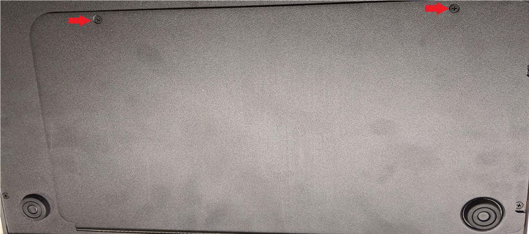
Flip the unit over to access the fader port. Remove the two screws and remove the cover.
Step 4
Disconnect the fader electrical connections by pulling gently.
Step 5
Remove the fader
TO INSTALL A NEW FADER, REVERSE THE PREVIOUS STEPS
Step 6
Insert the new replacement fader. Replace with Penny & Giles 104mm Linear Manual Fader PGF3210.
Step 7
Reconnect the fader electrical connections.
Step 8
Replace the rear panel and back access screws.
Step 9
Replace the two fader screws.
Step 10
Replace the fader knob.
Declaration of Conformity
Manufacturer’s Name: Sound Devices, LLC
Manufacturer’s Address: E7556 State Road 23 and 33
Reedsburg, WI 53959 USA
We, Sound Devices LLC, declare under our sole responsibility that the product:
Product Name: CL-16
Model Number: CL-16
Description: Linear Fader Control Surface for 8-Series
is in conformity with the essential requirements of the following relevant Union harmonisation legislation:
| Electromagnetic Compatibility Directive | 2014/30/EU | |
| Low Voltage Directive | 2014/35/EU | |
| RoHS Directive | 2011/65/EU |
The following harmonized standards and/or normative documents were applied:
Safety EN 62368-1:2014
EMC EN 55032:2015, Class B
EN 55035:2017
This Declaration of Conformity applies to the above-listed product(s) placed on the EU market after:
February 11, 2020
Date Matt Anderson - Sound Devices, LLC President
This product incorporates software subject to the BSD license: Copyright 2001-2010 Georges Menie (www.menie.org)
All rights reserved. Redistribution and use in source and binary forms, with or without modification, are permitted provided that the following conditions are met
* Redistributions of source code must retain the above copyright notice, this list of conditions and the following disclaimer.
* Redistributions in binary form must reproduce the above copyright notice, this list of conditions and the following disclaimer in the documentation and/or other materials provided with the distribution.
* Neither the name of the University of California, Berkeley nor the names of its contributors may be used to endorse or promote products derived from this software without specific prior written permission.
* THIS SOFTWARE IS PROVIDED BY THE REGENTS AND CONTRIBUTORS ``AS IS’’ AND ANY EXPRESS OR IMPLIED WARRANTIES, INCLUDING, BUT NOT LIMITED TO, THE IMPLIED WARRANTIES OF MERCHANTABILITY AND FITNESS FOR A PARTICULAR PURPOSE ARE DISCLAIMED. IN NO EVENT SHALL THE REGENTS AND CONTRIBUTORS BE LIABLE FOR ANY DIRECT, INDIRECT, INCIDENTAL, SPECIAL, EXEMPLARY, OR CONSEQUENTIAL DAMAGES (INCLUDING, BUT NOT LIMITED TO, PROCUREMENT OF SUBSTITUTE GOODS OR SERVICES; LOSS OF USE, DATA, OR PROFITS; OR BUSINESS INTERRUPTION) HOWEVER CAUSED AND ON ANY THEORY OF LIABILITY, WHETHER IN CONTRACT, STRICT LIABILITY, OR TORT (INCLUDING NEGLIGENCE OR OTHERWISE) ARISING IN ANY WAY OUT OF THE USE OF THIS SOFTWARE, EVEN IF ADVISED OF THE POSSIBILITY OF SUCH DAMAGE.
Two Level Segregated Fit memory allocator, version 3.1.
Written by Matthew Conte
http://tlsf.baisoku.org
Based on the original documentation by Miguel Masmano:
http://www.gii.upv.es/tlsf/main/docs
This implementation was written to the specification of the document, therefore no GPL restrictions apply.
Copyright (c) 2006-2016, Matthew Conte All rights reserved.
Redistribution and use in source and binary forms, with or without modification, are permitted provided that the following conditions are met:
* Redistributions of source code must retain the above copyright notice, this list of conditions and the following disclaimer.
* Redistributions in binary form must reproduce the above copyright notice, this list of conditions and the following disclaimer in the documentation and/or other materials provided with the distribution.
* Neither the name of the copyright holder nor the names of its contributors may be used to endorse or promote products derived from this software without specific prior written permission.
** THIS SOFTWARE IS PROVIDED BY THE COPYRIGHT HOLDERS AND CONTRIBUTORS “AS IS” AND ANY EXPRESS OR IMPLIED WARRANTIES, INCLUDING, BUT NOT LIMITED TO, THE IMPLIED WARRANTIES OF MERCHANTABILITY AND FITNESS FOR A PARTICULAR PURPOSE ARE DISCLAIMED. IN NO EVENT SHALL MATTHEW CONTE BE LIABLE FOR ANY DIRECT, INDIRECT, INCIDENTAL, SPECIAL, EXEMPLARY, OR CONSEQUENTIAL DAMAGE (INCLUDING, BUT NOT LIMITED TO, PROCUREMENT OF SUBSTITUTE GOODS OR SERVICES; LOSS OF USE, DATA, OR PROFITS; OR BUSINESS INTERRUPTION) HOWEVER CAUSED AND ON ANY THEORY OF LIABILITY, WHETHER IN CONTRACT, STRICT LIABILITY, OR TORT (INCLUDING NEGLIGENCE OR OTHERWISE) ARISING IN ANY WAY OUT OF THE USE OF THIS SOFTWARE, EVEN IF ADVISED OF THE POSSIBILITY OF SUCH DAMAGE.